
General Guidelines
For specific valve applications, Metcraft provides supplemental information with each shipment. Please refer to these sheets for answers to specific questions on individual valves. In general, Metcraft’s pneumatic valves are designed to operate with atmospheric air pressure under these general guidelines:
- Water lines supplying pneumatic valves must be a minimum of 1/2” ID.
- All valves require water pressure of at least 35 PSI flowing. Recommended maximum pressure 70 PSI.
- Flow controls of lavatories/drinking fountains are preset to .5 gallons per minute.
- Flow controls of showers are preset with 2.5 gallons per minute for standard application or as required.
- Flush all standing water from lines prior to attachment of valve to water supply. Do not leave highly chlorinated water in valves during the sanitation process or severe damage will occur. Long periods of dormancy can adversely affect valves. The water should be removed from valves during such dormant periods.
For the best results from Metcraft’s A300 Pneumatic Valves, reasonable water quality standards must be maintained. High levels of minerals and sediments in water supply will have detrimental effects on function of these valves.
Installation Instructions
- Flush all supply lines thoroughly before hooking valves to supply lines.
- Make sure polyethylene tubing is clear of any debris or water. DO NOT use kinked tubing.
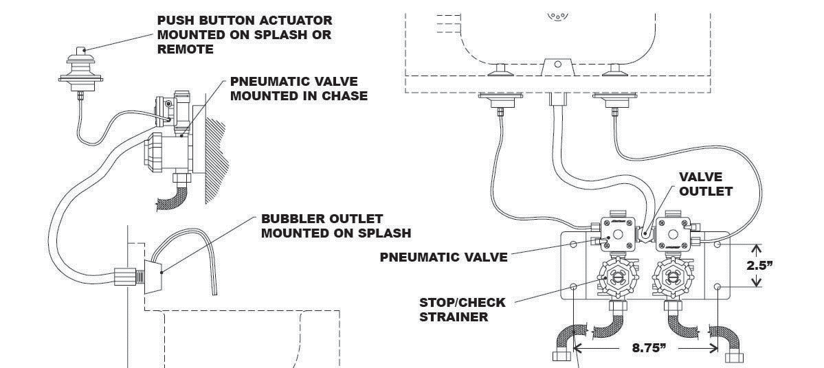
- Install inlet fitting to the bubbler/shower head. Assemble push buttons and bubbler/shower head to the fixture’s backsplash/panel before securing to the wall.
- Mount the valve and bracket assembly to the wall. Choose a location where future access for maintenance and adjustment of the valve will be convenient. The valve must be located within 7 feet of the push button operators and bubbler outlet.
- DO NOT use pipe thread compounds or sealants on any threads connecting to the valves, valve operators and tubing nuts. Thread sealants are not intended for these connections and may contribute to valve damage or malfunctions and thereby void warranty.
- Connect 1/2” polyethylene tubing to the bubbler/shower head and the valve outlet. Loop tubing below spout to prevent water draining from spout. Compression connections should be tightened. Over-tightening with a wrench may cause damage. Make sure tubing is fully inserted into socket before tightening.
- Connect 1/8” tubing to push button assemblies and to brass barb connection on the side of the valve operator. Make sure tubing is fully inserted in socket on push button assemblies before tightening small plastic nut. Small nut should be finger tightened only. Do not use a wrench on these nuts.
- Open supply stop(s) and check the valve connections for leaks.
- Actuate push buttons several times to clear air from the valves and tubing. Check water tubing at valve and bubbler for possible leaks again.
- Adjust timed cycle of valves as needed, following the instructions given below.
The timing cycle can be adjusted using the timing adjustment located next to the 1/8” air tube connection on the side of the valve operator. These valves have a small screwdriver slot on the end of the adjuster. Timing clockwise lengthens the cycle; counter-clockwise shortens the cycle. Adjustments should be made in small increments to achieve best results. As the cycle is lengthened, adjustments become increasingly sensitive. Timed cycles in excess of 1 minute require infinitely small adjustments.